
1Five minutes to a first drive
- Open the app. A single 15-tooth, module 2 spur gear is the driver (#1). It is always the root of the train.
- Add New puts a second gear on it, meshing. Select it in the Gears list and set
Number of teeth (N)— the ratio in the list updates as you type. - Turn the connection. Connection properties ·
Directionswings the child around its parent; the centre distance stays correct. - Press Space (or Start/Stop). The train turns at the drive speed. Drag the dot on tooth 0 to turn it by hand when stopped.
- Check the numbers.
Info(top right, orI) opens the data box: diameters, contact ratio, working pressure angle, tooth forces. - Export. Select a gear →
DXF selectedfor cutting,STLfor printing.SVG allgives a drawing of the whole train.
Everything is saved in the browser as you work. Save writes a .gg file; Copy share URL puts the whole design in a link.
2How a design is put together
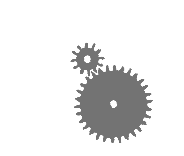
The train is a tree. Every object hangs off one parent by a connection:
- Gear (mesh) — the two mesh; the centre distance follows from the teeth, module and profile shift, and the direction is yours to choose.
- Axle — the child sits on the same shaft: same centre, same speed, new layer.
A layer is one shaft line. Visibility · Same layer shows only the layer of the selection, which is how you work on a multi-stage box. The 3D view always shows one layer.
Ratios come out of the tree: the Gears list shows each object's ratio to drive 1 and its rpm, signed by direction (the info box spells out ↺ CCW / ↻ CW).
What can connect to what
| gear | internal | rack | planetary / chain / belt | |
|---|---|---|---|---|
| gear | axle, mesh | axle, mesh | mesh | axle |
| internal | axle, mesh | axle | — | axle |
| rack | mesh | — | — | — |
| planetary / chain / belt | axle | axle | — | axle |
A rack cannot be the driver. Type buttons that would break an existing connection are disabled and say why.
3The stage
| Action | Result |
|---|---|
| Click | select (click again, or empty space, to deselect) |
| Drag | pan |
| Wheel | zoom about the pointer |
| Double-click | fit everything |
| Drag the tooth-0 dot (stopped) | turn the whole train by hand; let go to throw it |
F / S / C / 1 | fit all / selection / selection with its neighbours / real size |
Space | start–stop · Delete remove · Ctrl/Cmd+Z undo |
100% means real size on screen at 96 dpi: hold a caliper to the screen and the pitch diameter is right. The bottom right corner always shows the current scale.
Overlays (Display section): gear guides (root, base, reference and tip circles), gear labels, centre marks, curve types (involute / trochoid / tip / root drawn in different colours), Bézier nodes for the selected object and its neighbours, and the line of action with live contact points. The same section holds Lost motion, which is a simulation setting rather than an overlay (§6.2). The 3D view draws the guides, labels, centre marks and the line of action too: the line of action of every mesh on show, over everything, on the top face the two gears share. Curve types and Bézier nodes are 2D only.
This manual, while you work. Help (H) shows it in a panel on the stage, where the info box sits, so you can read it with the gears still in front of you and still turning; Esc or Help again puts it away. The manual and the info box share that corner: opening one closes the other. It is this same page, not a copy, so everything in it works there: the contents, the § links, the figures. The link at the top right of its bar, open in new window, hands it to a tab of its own and puts the panel away — Shift-click Help does the same without opening the panel first. Below about 1000 px of window there is no room for it beside the gears, so Help opens the page instead; widen the window and the panel comes back if that is how you left it. The website opens without the manual and the info box; the desktop app opens them as you left them.
4Designing gears
4.1Spur gear

| Control | Range | Notes |
|---|---|---|
| Number of teeth (N) | 4 – 400 | Shift+Enter keeps the diameter and changes the module instead |
| Module (M) / Diametral pitch (P) | 0.05 – 100 mm | shared by everything that meshes with this gear |
| Pitch diameter (D) | — | Enter changes the teeth count, Shift+Enter the module |
| Pressure angle (PA) | 10° – 35° | 20° standard; 14.5° for old work, 25° for strength |
| Profile shift (x) | −1 – 2 | No undercut sets the smallest shift that avoids undercut |
| Backlash | 0 – 5 mm | circumferential tooth thinning of this gear; watch it as lost motion (§6.2) |
| Face width | 0.1 mm + | in the 3D view; drives STL/OBJ only |
Geometry follows the standard rack: addendum 1·m, dedendum 1.25·m, so root clearance is 0.25·m. The flank is a true involute; the fillet is the trochoid the generating rack's tip corner traces, so undercut appears exactly where a hobbed gear would have it — that is also why the app can warn about it rather than guess.
The info box reports reference, base, tip and root diameters, the diameter where the involute starts (Involute starts Ø — below this the flank is fillet, not involute), circular pitch, Béziers per tooth and the worst fit error of the curve fit (§9).
4.2Internal (ring) gear

Same parameters plus Rim thickness (material outside the roots); teeth run from 12 to 400. Rules the app enforces or warns about:
- The ring needs at least one more tooth than the largest gear meshing with it (hard limit), and 8 more to avoid interference in practice (warning).
Pinion tips hit the bottom of the ring's tooth spacesmeans the pair as drawn would not assemble — raise the ring's teeth, lower the pinion's, or shift the profiles.- Where a space closes up before the root (high pressure angle or shift), the bottom is cut the way a pinion-type cutter would cut it, instead of letting the flanks cross. The shape you get is what a shaper can actually produce.
Ring gears take screw holes in the rim (§7).
4.3Rack

Teeth, Module, Pressure angle, Body height (material below the roots), and Display:
- Fade — a window of rack fades out past the contacts (drawing style).
- Cut — the same window with hard ends.
- Length — a finite rack of
Teethteeth that travels; when it runs past the end it wraps by whole teeth so it never leaves the screen.
Contact distance places a rack child along its parent's rack, measured from the parent's contact point. The info box gives the rack's travel in mm/min at the current speed — the number you need for a feed calculation.
In the exports the rack is a piece of whole teeth. In Fade and Cut mode the piece follows the animation and jumps back one tooth each tooth of travel; export in Length mode when you want a definite bar.
4.4Planetary set

Sun gear (SN), Planet gears (PN), Ring gear (RN), Number of planets, Auto profile shift, Backlash, Ring rim, and the roles.
Two rules govern the set, both checked live:
- Teeth:
RN = SN + 2 · PN, or the planets cannot mesh with both sun and ring. - Assembly:
(SN + RN) / nmust be a whole number, or the planets cannot be spaced equally. The app then places them on the nearest valid tooth positions and warns.
Planetary setup gives each member a role: Input (driven by the parent), Fixed, Drive (its own drive — a differential), Output (children hang off it). The ratio follows: with the ring fixed, carrier / sun = SN / (SN + RN); the info box always shows the actual Output / input ratio for the roles you chose.
Auto profile shift applies the no-undercut shift to the sun and planets and balances the ring to keep both meshes right; the info box lists the three shifts used. Contact ratios for sun–planet and planet–ring are listed separately — check both.
The carrier is drawn as thin dashed arms; select the set to dimension them (radius of the planet axes and the angles between the arms).
4.5Chain wheel set

Pick an ISO 606 / ANSI chain (04C, 05B, 06B, 06C, 08A, 08B, 10A, 12A, 16A) and the two tooth counts. The tooth form is the simplified ISO 606 profile: roller seat radius ri = 0.505·d1 + 0.069·∛d1, seating angle (140 − 90/N)°, flank radius re = 0.008·d1·(N² + 180), tip between the standard minimum and maximum.
Wheel distance (D) is a target: the real distance in brackets is the nearest one that gives a whole, even number of links (so the chain closes with the same link types). The info box gives the link count, the chain length and both pitch diameters.
The chain also decides how the sprocket is built. A sprocket has to run between the chain's inner plates, so its toothed body is not a face width you choose: it is the ISO 606 tooth width for the chain you picked — 0.93·b1 up to 12.7 mm pitch and 0.95·b1 above, where b1 is the width between the plates. The app fixes it, states it in the 3D properties and in the info box, and gives you the two things that really are yours:
- Tooth chamfer — what lets the chain roll on and off instead of catching a square corner. It is a shallow cone turned onto the outer edge of the wheel: it starts where the roller seats end and the tooth flanks begin, and sinks towards the tips at the angle you give (
Auto= 10°, a workshop chamfer), so the tips lose the most and the seats the rollers sit in keep their full width. It changes the solid only: the 2D outline, and the SVG and DXF exports, stay the flat profile you would cut. - Hub — the collar around the bore, per sprocket:
None,One side(flush with the teeth on the other face, as most machined sprockets are) orBoth sides. Its width is the whole width of the wheel at the hub and can never be less than the body; its diameter is capped by what the chain plates clear where they wrap onto the wheel,p·cot(π/N) − 1 − h₂(ISO 606) — the field shows that limit, and a hub asked to be fatter is trimmed to it with a . A hub too small to leave material around its own bore is left out and reported.
Holes and screw holes are set as usual (§7): the ones that fit inside the hub are bored through it, giving the grub screw or the shaft a proper length of grip, and any outside it go through the body alone. The hub is drawn as a thin circle in 2D, and comes out in the STL and OBJ solids; in SVG and DXF it lands in the optional guides layer, because a flat-cut part has no hub.
In the 3D view the chain itself is drawn: outer and inner links in turn, with their rollers and pins, wrapping both sprockets and running as the set turns — which is also the easiest way to see whether a hub is too fat for the plates to pass over. Every size of a link is that chain's own — plate depths, roller and pin diameters, and the width over the plates — in 2D as in 3D, so a roller always fits the seat the sprocket is cut with.
4.6Belt wheel set

Presets: GT2 2 mm and 3 mm, HTD 3M / 5M / 8M, T5, T10, and a flat belt. Choose the two tooth counts; Wheel distance is again a target, snapped to a whole number of belt teeth. The info box gives the belt tooth count, the pitch length and both pitch diameters — the numbers you order a belt with.
Sprockets and pulleys are always spur; there is no helical option for them.
5Profile shift and undercut

Profile shift moves the cutting rack in or out by x·m:
- Positive shift on a small pinion removes undercut, thickens the root and raises the tooth; it also pushes the pair apart (the working pressure angle rises).
- Negative shift brings a pair closer together than the standard centre distance.
- A pair keeps meshing at the centre distance the app computes from both shifts — it is never the naive
m(N₁+N₂)/2unless both shifts are zero.
No undercut uses x ≥ 1 − N·sin²α / 2. The warning Undercut: consider a profile shift appears only when the undercut actually eats into the involute (the involute start radius is more than 2 % above the base circle) — a hair of undercut on a large gear is not flagged.
Watch the contact ratio while shifting: below 1 the pair loses contact between teeth, and the app marks it in red in the info box and warns in the list.
6Backlash and lost motion
6.1What backlash does here

Backlash is a circumferential value in millimetres, entered per gear (and once per planetary set, where it is shared by both meshes). Each flank of the gear is thinned by half of it, so a pair with 0.2 mm on each gear has 0.4 mm of circumferential play.
What the app does with it:
- The teeth are really thinner — it is in the outlines, the DXF, the STL, everything.
- The driven member takes the gap up, so the flanks that carry the load touch and the trailing flanks show the gap. This holds for external pairs, internal meshes and both meshes of a planetary set.
- Direction matters. Reverse the drive (
Rev) or drag a gear the other way by its marker and the contact moves to the other flank, as it does in a real drive. - So does where you push. Turning the train by a wheel in the middle of it makes that wheel the source: it drives the gears after it in the usual way, but it also back-drives everything between it and the first gear, so those meshes take their play up on the opposite flank — again, as in a real drive when you turn an output shaft by hand.
6.2Lost motion — the dead band, simulated
Backlash on a drawing is a number per mesh. What you actually feel at a shaft is lost motion: the angle the input can turn, after a reversal, before the output moves at all. It is the sum of every mesh's play referred through the ratios, and it is what decides whether a positioning drive can repeat a move, whether a reversing load will hammer, and how much of a servo's resolution a gearbox throws away.
Lost motion (Display · Lost motion, on by default) simulates it properly rather than drawing it. Each mesh is a dead band: the driven wheel is pushed by one flank, and when the driver reverses it stands still until the other flank comes round to it. Reverse the drive (Rev) and watch a three-gear train: the first gear turns alone; the second waits out its gap, then starts; only then does the third begin to wait out its own. The delays add up down the train, one mesh at a time, exactly as the real one does.
Reading your design's lost motion off the screen. Freeze the animation, then take the output wheel by its first-tooth marker and turn it in the direction that unloads it. It will turn freely while the gaps close one after another, and the input gear will not move at all — the angle the output covers before the input twitches is the lost motion of your train, referred to the output shaft. Turn it back the other way and the whole train follows instantly, because those flanks are already touching. That asymmetry is real, and it is the same thing you feel with a shaft between your fingers.
Other things the simulation shows you:
- No contact means no contact. While a mesh sits inside its gap neither flank is touching, so its contact dots disappear and the info line counts it as 0 tooth pairs in contact. The line of action stays drawn — that is where the teeth will meet. Over a reversal you can watch contact leave one flank, vanish, and arrive on the other.
- Where you push matters. Turning the train by a wheel in the middle makes that wheel the source: the wheels after it follow through their own gaps, and the wheels between it and the drive are back-driven through theirs, one at a time, before the drive itself moves.
- It does not drift. However long the animation runs, and however many reversals, a mesh that has been driven one way sits exactly on its flank again — the state is pinned, not integrated.
Switch it off to compare, or to read the exact meshing position of a train under load: the take-up then closes the whole gap the instant the direction changes, as a drawing would show it.
What is not in it: torsional windup of shafts and teeth, friction, inertia (a free wheel does not coast through its gap — it waits to be pushed), bearing and keyway clearance, and chain or belt slack. The number you read off is the geometric lost motion of the gearing alone, which is the part you can do something about while designing the teeth.
One simplification: a planetary set takes its two meshes (sun–planet and planet–ring) up together rather than one after the other, so a set behaves as a single dead band of the size of both. The total is right; only the order within the set is not.
6.3Choosing a value
Circumferential, total per mesh:
| Case | Typical |
|---|---|
| Machined metal, general | 0.03 – 0.06 · m |
| Laser-cut plate, acrylic or ply | 0.1 – 0.2 mm on top of the kerf |
| FDM 3D printing | 0.2 – 0.4 mm (your printer's over-extrusion decides) |
| Positioning drive where lost motion matters | as little as fits, and shift instead of thinning |
Backlash is not the same as the root clearance (0.25·m, always present) and not the same as the centre-distance tolerance; if you widen the centre distance instead, use a positive shift rather than thinning the teeth.
7Holes, joints and screw holes

Per wheel (Holes & shaft joints):
| Type | Parameters | Standard |
|---|---|---|
| Round | Ø | — |
| D-flat | Ø, across the D | — |
| Double-D | Ø, across flats | — |
| Keyway | Ø | key from DIN 6885 for the bore |
| Hex / Square | across flats | — |
| Nut traps | nut size, count, bolt circle, bore, clearance | ISO 4032 (M2 – M12) |
Screw holes are a bolt circle: number of holes, bolt circle radius, hole diameter, and a rotation for the first hole. On a ring gear they sit in the rim.
The app will not produce a part that cannot exist:
- A hole that would break into the teeth, into the centre hole or into its neighbour is left out, and the reason appears as in the list and in the info box.
- The same for a centre hole larger than the wheel allows.
- The limit is the tooth roots less 0.8 · module, with at least 0.8 mm of material between holes. If a hole is dropped, either shrink it, move the bolt circle, or give the wheel more material (a bigger rim on a ring, more teeth on a gear).
Bores are drawn at their nominal size — add your own fit allowance (H7/h6 as your process needs, or 0.1 – 0.3 mm for printed parts).
8Tooth form in 3D: helical, double helical, herringbone

Press 3D to enter the 3D settings view. It shows the layer of the selection as solids and holds the settings that only exist in 3D. The Gears list is there to select from; adding, removing and clearing wait for the 2D view, where a new gear's teeth, module and connection are set:
| Control | Notes |
|---|---|
| Tooth form | Spur · Helical · Double · Herringbone |
| Helix angle β | 1° – 45°; shared by every gear that meshes |
| Hand | Right / Left; flips across an external pair, stays across an internal mesh or a rack |
| Groove width | double helical only; Auto = a quarter of the face width |
| Face width | per object |
| Tooth chamfer, Hub | chain wheel sets only (§4.5): the chamfer on the teeth, and a hub per wheel |
A chain wheel set has no face width to set — the chain fixes the toothed body, and the panel says how wide it is and why. Its 3D section holds the tooth chamfer and the two hubs instead (§4.5).
Module and pressure angle are normal values. A helix angle converts them into the transverse plane the profile is cut in:
m_t = m_n / cos β tan α_t = tan α_n / cos β x_t = x_n · cos βSo the 2D outline, every diameter and every centre distance grow by 1 / cos β. The panel shows a line saying so, and the info box lists the transverse module and transverse pressure angle next to the normal ones you entered. At β = 20°, a 15-tooth m2 gear has D = 31.93 mm, not 30 mm.
What to check in the info box:
- Overlap ratio εβ =
b · sin β / (π · m_n). Aim for ≥ 1 if you want the smooth running helical gears are chosen for; below 1 the face is too narrow for the helix angle. - Axial force Fa =
Ft · tan βper mesh — the load your bearings have to take. Double helical and herringbone report balanced instead, because the two halves cancel. - Hands: for a planetary set the sun carries the set's hand and the planets and ring take the other.
The twist is about the mid-plane, so the section at half the face width is exactly the 2D profile and conjugate partners mesh in every slice. Holes and ring rims stay straight.
9Accuracy
9.1What the curves are

- Involute flanks are fitted with cubic Béziers to a tolerance you set — they are not polylines and not arc approximations.
- Fillets are the true trochoid of the generating rack's tip corner, including undercut.
- Tip and root arcs are exact circular arcs (as exact as a cubic arc can be, error < 0.02 % of the radius per 90° segment).
- Circles (guides, bores, bolt circles) are exact arcs.
Curve precision (Document section) is the largest distance a Bézier may sit from the exact curve. Default 2 µm; range 0.1 µm – 50 µm. It drives the stage, the SVG, the DXF, the meshes — everything.
The info box reports, per gear:
- Béziers per tooth and the total for the outline;
- Max fit error in µm — the worst actual deviation of the fitted curve from the exact involute for this gear. This is the number to quote when someone asks how accurate the profile is.
At the default setting a typical gear comes out with a handful of segments per flank and a fit error well under a micrometre — smaller than any cutting process will hold.
9.2Accuracy of each export
| Output | Geometry | Practical limit |
|---|---|---|
| SVG | exact cubic Béziers; straight pieces as lines | whatever your CAM reads; no sampling loss |
| DXF (R12) | outlines sampled into POLYLINEs at the curve precision (never coarser than 0.5 µm) | R12 has no splines — the sampling is the only loss |
| STEP (desktop app) | exact solids: the outlines' Béziers are the faces' own B-spline curves; a helical twist is fitted along the face width within a quarter of the curve precision (at least 0.5 µm); Pro's 3D gear pairs and chain sprockets are surfaces fitted through their slices within the curve precision (at least 5 µm) | none for straight faces; the fit for twisted and 3D surfaces |
| STL / OBJ | triangulated from the same curves, sampled at the curve precision but never coarser than 5 µm; twisted faces sliced by sagitta | facet size; watertight, one closed solid per part |
| 3D view | the same solids at a coarser tolerance (5 × curve precision, at least 10 µm) | preview only — the exports are finer |
Exports carry marks, labels and guides according to the Display checkboxes, on their own layers/groups, so you can switch them off for a cutting file and on for a drawing.
A STEP file (AP214, millimetres) opens in any CAD program as solids you can edit, measure and machine: every part is a named body of its own. STEP – All Gears places them as they stand on the stage, in the pose of the animation, so they mesh; the layers stand one above the other, a millimetre apart. STEP – Selected exports a gear on its own axes, centred on the origin, and a planetary set or a chain or belt drive as it stands. Racks, rings, holes, helical, herringbone and double helical teeth all come out as solids; chains and belts do not.
The All Gears exports (SVG, DXF and STEP) hold the gears of the stage only. Gear Generator Pro's 3D gear pairs are not among them: a pair is exported on its own, while it is selected (§14.1).
9.3What is verified, and how
The geometry is covered by an automated test suite (88 tests, run with npm test), not judged by eye:
- Conjugate action: external pairs (with shifts and backlash), internal pairs, racks and planetary sets are sampled at many angles and the outlines checked for overlap — penetration stays at the sampling noise (a few micrometres), i.e. the flanks roll without digging in.
- Backlash take-up: with 0.4 mm of backlash the outlines pass within ~1 µm of the contact points the line of action predicts — the load side really touches, in both directions, and whichever wheel of the train the hand turns (including the meshes that then run backwards).
- Lost motion: the wait is exactly the width of the gap and not a hair more, it passes down a train mesh by mesh, no teeth dig in anywhere along the crossing, and the state neither widens nor drifts after hundreds of reversals — a long run one way puts every mesh back on its flank to the last digit.
- Ring gears: the outline never crosses itself over a wide sweep of pressure angles and shifts, and the pinion always clears the space bottoms.
- Solids: every tooth form (spur, helical, double helical, herringbone) on gears with keyways, on rings and on racks comes out as a closed 2-manifold with the expected volume; helical partners are checked slice by slice.
- Sprockets: every chain, a wide range of tooth counts and each kind of hub give a closed solid of the volume the body, the hub and the holes add up to; every vertex of a chamfered wheel is shown to lie on the cone the chamfer angle describes, with the roller seats at full width; a hole on the hub is bored through it and one outside it is not; and the chain links come out closed, alternating and one pitch apart along the path.
- Units and I/O: unit maths,
.gground trips, share links and Gear Generator 2 import.
9.4What the app does not compute
It is a geometry and kinematics tool. It does not do:
- strength, stress, Lewis/AGMA/ISO 6336 ratings, or material selection;
- efficiency, friction or losses — all torques are ideal (power in = power out);
- lubrication, temperature, noise, or dynamic effects;
- tolerance stack-ups, fits, or manufacturing allowances (kerf, shrinkage, over-extrusion);
- bevel, worm, hypoid or non-circular gears;
- chain wear, elongation or the sag of a long span — the chain is drawn at its nominal pitch, running on the pitch polygon, and the links are rigid.
Treat its numbers as exact geometry, and your own engineering judgement as the rest.
10Loads and forces

Set the input on drive 1: Torque (N·m) or Power (W); the line under it shows both. Load flows down the tree, split at branches by Load share (Auto divides equally).
The info box, per object, gives:
- Torque and Power at that object;
- Tooth forces with each neighbour: tangential
Ft, radialFr = Ft·tan α_w, axialFa = Ft·tan β(helical), and the resultant normal forceFn— the load for a bearing calculation; - Chain / belt tension and an approximate shaft load (twice the tension);
- Planetary: sun, carrier and ring torques and the force per planet mesh.
Working pressure angle α_w is used, not the nominal one, so shifted pairs give the right force directions.
Planetary sets with a second drive. The three member torques are in fixed ratios Ts : Tr : Tc = 1 : RN/SN : −(1 + RN/SN), so only one load can be set: drive 1's. A second drive's load box is read-only and shows what its member must supply, labelled Coupled to Drive 1. A member held at 0 rpm carries torque but no power — that is correct, not a bug.
11Warnings
Every warning appears as next to the object in the Gears list, with the text in the info box.
| Warning | What it means |
|---|---|
| Undercut: consider a profile shift | the fillet is eating the involute; raise the shift or the teeth count |
| Contact ratio n < 1 with #id | the pair loses contact between teeth — more teeth, less shift, or a smaller pressure angle |
| Module / pressure angle differ from the mating gear | these are shared by a mesh group; something was set outside it |
| Tooth form / helix angle differ from the mating gear | the same for the 3D tooth form |
| Internal gear needs at least 8 more teeth than the pinion | interference risk in a real cut |
| Pinion tips hit the bottom of the ring's tooth spaces | the pair as drawn cannot assemble |
| Ring teeth must equal sun + 2 × planet teeth | a planetary set cannot mesh otherwise |
| Planets can't be equally spaced: (Ns+Nr)/n = … | pick a planet count that divides, or accept uneven spacing |
| Planets collide with each other | fewer planets, or smaller planets |
| No room for the centre hole / screw holes: left out | the hole was dropped; see §7 |
12Recipes
A two-stage reducer. Driver 15 T → mesh a 45 T (3:1). Select the 45 T, Add New, set the new gear's connection to Axle — it is now the second shaft. Mesh another gear on that, 15 T → 60 T (4:1). The list shows 12:1 overall. Use Visibility · Same layer to work on one shaft at a time.
A planetary gearbox. Add a planetary set. Sun 12, planet 9, ring 30 (30 = 12 + 2×9 ✓, (12+30)/3 = 14 ✓ for 3 planets). Roles: sun Input, ring Fixed, carrier Output → ratio 1 : 3.5. Check both contact ratios in the info box, then set Auto profile shift if the sun is small.
Rack and pinion travel. Mesh a rack on a gear. The info box gives travel in mm/min at the drive speed; travel per revolution = π · m · N. Export in Length mode to get a definite bar.
A printed helical pair. Design the pair in 2D first (the numbers are normal module values). Press 3D, choose Helical, set β = 15–20° and a face width of at least π·m / sin β to keep εβ ≥ 1. Add 0.2 – 0.3 mm of backlash for FDM. Export both gears as STL — they are closed solids, no repair needed.
Laser-cut plate gears. Keep the tooth form spur. Add backlash equal to your kerf plus a little (0.15 – 0.25 mm typical). Switch off labels and guides in Display, then DXF selected per part, or DXF all for a nested sheet.
A sprocket you can fit to a shaft. Add a chain wheel set and pick your chain: the toothed body is now as wide as that chain allows, which on a small pitch is only a few millimetres — not enough to grip a shaft. Press 3D, set the primary wheel's Hub to One side, and give it a width that suits the shaft (a bore's worth of grip is a fair rule) and a diameter within the limit the field shows. Back in 2D, put the bore and a couple of screw holes on a bolt circle that stays inside the hub — the note under the screw holes says how far that reaches — so the screws are drilled through the full hub. STL selected exports the sprocket as one closed solid, chamfered teeth, hub and all. The flat SVG or DXF of the same wheel is the plain profile, as it must be: a laser has no way to cut a hub.
Measuring the lost motion of a train. Enter the backlash you can really hold on every gear, leave Lost motion on, and press Freeze. Note where the last gear's tooth-0 dot sits, then drag that dot in the direction that unloads the train: it turns freely, mesh after mesh, while the first gear stands still. The moment the first gear twitches, stop — the angle the output has covered is the lost motion of the whole train at the output shaft (§6.2). Halve a mesh's backlash, or move the big ratio nearer the output, and repeat to see what it buys you.
13Files, sharing and compatibility
.gg— the whole document as JSON.Save/Open…. Older files are upgraded silently, and.gg3files from the first web versions open too.- Share URL — the entire design compressed into the link; nothing is stored on a server.
- Gear Generator 2 —
Import URL…reads a GG2 share link;Open…reads a GG2.ggfile (the same extension: the two are told apart by what is inside). GG2 chains map to the nearest preset. - Autosave — your work is kept in the browser between sessions.
- The view is kept with the document: 2D or 3D, where the stage was panned and zoomed to, and the 3D view's turn, tilt and zoom. The page reloaded, the desktop app started again or a
.ggfile opened, you see what you saw when you left it. A share link opens fitted to the stage, as before. - Export passes — exports are gated by a time-limited pass: without one the export buttons are greyed out, and
Get an export passunder them opens the store; with one the panel shows the time left. A pass works in three browsers at a time: in another one, chooseAlready paid?in the store and enter the 6-digit code it e-mails to the address you bought the pass with (or open the e-mail's link there). The same sheet sells the Gear Generator 3 Desktop App (45 EUR): a lifetime license that works offline, on macOS (Apple silicon and Intel), Windows and Linux, on 3 computers, every export included, with free minor updates and the next major version at a reduced upgrade price. Its license key comes by e-mail, with the link to the download page. The desktop build has no store.
The desktop app (Mac, Windows, Linux) works from its menus instead of the panel's Document, Export and Display sections: File › New, Open…, Close, Save, Save As…, Import › Share Link… (a GG3 or GG2 link), Export › SVG / DXF / STEP / STL / OBJ, Copy Share Link; Edit › Undo, Redo; View › 2D / 3D, the zooms, the info box, the display settings, the unit system and the colour theme; Help › the manual, in a window of its own. Double-click a .gg file to open it. A Gear Generator 2 file is converted to the new format the first time you save it, after asking (Save As… keeps the original). Closing or quitting asks about unsaved changes, and the last document is there again the next time the app starts. The app bought on geargenerator.com asks once for the e-mail address and license key from the purchase e-mail; a key works on three computers, and License… moves it to another one (deactivate it there first: a fourth computer is turned away). Once registered, the app works offline. The Mac App Store edition needs no key.
When a new version is out, the app says so: at most once a day, as it starts, it asks geargenerator.com, sending only its name and version number. Download opens the download page in the browser, Later asks again tomorrow, and Skip This Version stays quiet until the next one. Check for Updates… (in the Gear Generator menu on the Mac, under Help elsewhere) asks at once. Without an internet connection nothing is asked, and nothing changes.
14Gear Generator Pro: 3D gears and web views
Gear Generator Pro is the desktop app with three things more:
- 3D gear pairs: worm gears, bevel gears and screw gears, whose axes cross, so a flat drawing can't show them.
- Web views: views of your setup for your own website, in 2D or 3D, still or turning. The website needs one script and one line of HTML for each web view.
- Back and forth: a drive that turns one way and then the other, eased at every turn (§14.5).
Pro is a separate app with its own license; a Gear Generator license does not open it, but a Pro license opens both.
14.13D gear pairs
The 3D Gears section of the panel, just below the Gears section, keeps gears whose axes cross. Each entry is a pair of two wheels that turn together and connect to nothing else:
- Worm gear — a worm and its wheel, the axes crossed at 90°. Every turn of the worm moves the wheel on by one tooth per start, so the ratio is large (30 teeth, 1 start: 30:1). With a small lead angle the wheel can't drive the worm back (self-locking).
- Bevel gear — two toothed cones, the axes meeting at the shaft angle (90° unless you change it; equal teeth make mitre gears). The teeth are
StraightorSpiral, with a spiral angle and the pinion's hand. An Offset moves the pinion's axis past the gear's, which makes the pair a hypoid. - Screw gear — two helical gears on axes crossed at 90°. Their helix angles add up to 90°, and both have the same hand.
The section works like the Gears section:
Add Newmakes a pair of the kind chosen last.Removetakes the selected pair away, andCleartakes them all. A web view that shows a pair goes with it: the app names those web views and asks first.Undobrings back the pair and its web views together.- Click a pair in the list to select it: - the view goes 3D and shows the pair in place of the gear's layer; - the gear's sections step aside for 3D gear type (
Worm,Bevel,Screw) and the pair's properties. - One thing is selected at a time. Selecting a gear lets the pair go, and so does going back to 2D (
2D,Esc). Selecting a pair lets the gear go. - The main drive turns the pair, as it turns the gears: its
Speedin the Animation section,Start/Stop,FreezeandReset. - It drives the first wheel: the worm, the pinion, gear 1. That wheel is shown as selected. - The other wheel follows at the ratio of the teeth. - The info line counts both wheels' turns, and the line under the properties gives both wheels' rpm. - The wheels carry what the gears carry, switched by the same Display settings: - labels, guide circles, centre marks; - a first tooth marker on a flat face of each wheel (a bevel gear's toe, its pinion's back, a worm's end).
- While the animation is stopped, drag a first tooth marker to turn the pair by hand; this turns the main drive. Let go while it is moving and the pair keeps turning, slowing to a stop.
- A self-locking worm can't be turned by its wheel. That is a worm whose lead angle is within the friction angle, about 5.7° (a single-start worm ten modules across); the line under its properties says so. Turned by hand, its wheel only crosses the backlash and stops at the thread, and without backlash it doesn't move. Every other pair turns from either wheel.
- Backlash plays as it does between gears (§6.2): - With Display ·
Lost motionon, the gap is a dead zone. Reverse the drive, or the hand on a marker, and the other wheel stands still until the gap is crossed. - A hand on the second wheel's marker makes that wheel the source: it pushes the driver through the gap. - WithLost motionoff, the gap is taken up at once, on the side the motion loads. - A web view can show a pair (§14.2): select the pair, then
Add Newin Web Views. Selecting a pair while a web view is selected puts the pair in that web view, as selecting a gear would. - Line of action (Display): where the teeth touch, over everything, in the accent colour. - Screw gears, and a worm with a cylindrical wheel: a straight line through the pitch point, along the flanks' normal. - A worm with a throated wheel: the line of action in the wheel's mid-plane. - Bevel gears: arcs of the plane of action on the spheres of the heel and the toe.
Each runs between where the teeth come into contact and where they leave it, for the flanks the drive loads now; it changes sides when the drive turns back.
- The info box (
I) shows the selected pair: - both wheels' sizes; - how they mesh: the sliding speed at the pitch point, the efficiency (friction μ 0.1), the backlash; - what they carry with Drive 1's load: both torques, the power in and out, and each wheel's tangential, axial and radial tooth force. A spiral bevel pinion's thrust is shown towards or away from the apex, and it flips when the drive turns the other way. - Exporting a pair (File › Export): while a pair is selected, the exports are the pair's, and say so. -
STEP – 3D Gear Pair…exports it as it meshes: both wheels in place, at the angle the animation has turned them to, as solids fitted through the wheels' slices within the curve precision. -STL – 3D Gear Pair…andOBJ – 3D Gear Pair…export each wheel laid out to print: standing on its axis, a bevel gear on its back. - TheAll Gearsexports are greyed out then, and so are SVG and DXF: a pair is not one of the stage's gears, and not a flat drawing. Select a gear, or go back to 2D, to export the gears of the stage. - Pairs are saved with the document in its
.ggfile, and undo works on them as on every change.
The properties:
- Module and Pressure angle: - worm gear: the worm's axial module, which is the wheel's transverse module; - bevel gear: at the large end of the teeth (the heel); - screw gear: the normal module, the same on both gears.
- Teeth of each wheel. A worm also has Worm starts: the number of threads, 1 to 6.
- Worm gear: - the worm's diameter (pitch diameter), hand and threaded length; - the shaft past both ends of the thread (length 0: none); - the wheel's face width, and the Wheel:
CylindricalorThroated. - Bevel gear: - the shaft angle; - the face width, measured along the cone, at most 45% of the cone distance; - the teeth (
Straight, orSpiralwith its angle and hand); - the Offset. - Screw gear: - gear 1's helix angle, 25° to 50° (gear 2 has the rest of the 90°); - the hand of both; - each gear's face width.
- Bores of both wheels. 0 means none, and a bore too big for its wheel is left out.
- Backlash: for a worm gear it comes off the wheel's teeth (measured at its pitch circle); for the others, half comes off each gear (a bevel pair's at the heel). The pair then plays it as described above.
The line under the properties gives the ratio, the centre distance (or, for bevel gears, the pitch cones and the cone distance), and the other sizes worth knowing.
How exact the pairs are:
- Bevel gears are cut as the gears are (§5), with a crown gear (a flat bevel gear) in the rack's place: - their flanks are spherical involutes, so the two gears mesh on every sphere around the apex; - the crown gear's tip corner rounds every tooth's root and undercuts the foot of a pinion with few teeth, as the rack undercuts a small gear. A bevel gear is undercut at the same tooth count as its equivalent spur gear (N / cos δ teeth). - A spiral is logarithmic: the same spiral angle along the whole face.
- Screw gears are involute helical gears, cut by the rack as every gear.
- The worm is an involute helicoid. Its wheel is one of two kinds: -
Cylindrical: an involute helical gear. The two are crossed helical gears and touch at a point, as most printed worm wheels do. -Throated: cut by the worm itself, as a hob cuts it, slice by slice across the face. Its teeth wrap round the worm in a throat and touch it along a line. The throat sits a quarter module clear of the worm's root, and the outer diameter is one module over the tip diameter. The face can be no wider than 1.8 × (worm radius − module); a wider one is made that wide, and the panel says so. - The tests check that the two wheels of every kind never overlap as they turn, down to 6-tooth pinions at 14.5°, and that every wheel is a closed solid whose faces never cross, at the extremes below too.
- With an offset, the pinion is fitted to the gear in the middle of the face, and both gears' teeth are made a little thinner so that they clear. The pair looks like a hypoid but is not generated as one: print it to look at, not to carry a load.
- At the extremes a bevel pair is made as near to what you asked as a solid can be, and every export is made from that: - With the shaft angle so wide that a pitch cone opens past 90°, that gear is an internal bevel gear: its teeth point inwards, as a ring gear's do. No crown gear can cut one, so its tooth foot is shaped as a ring's (§4.2): the involute, a fillet, then the root. - To reach the offset the pinion turns 25° at most; the teeth would be too thin past that. A larger offset is taken as far as that goes: the panel says so, and the info box gives the offset reached. - A pinion with few teeth at a small pressure angle, with much backlash or a large offset, can be thinned through at the narrow neck its undercut leaves. It is then thinned only as far as leaves the neck a tenth of a module wide, so it has a little less backlash than asked. A neck narrower than the tooth's top makes the tip pointier instead. - The teeth are never made coarser than a hundredth of the module, so a small module keeps its detail. - STEP fits its surfaces through the same slices, within the curve precision: the same solids, with smooth faces instead of facets. Checked in OpenCascade at these extremes too: each wheel one valid, closed solid, its volume within a fraction of a percent of the slices'.
14.2Web views in the panel
The Web Views section, at the end of the panel, works like the Gears section:
Add Newmakes a web view of what the stage shows now.Removetakes the selected one away, andCleartakes them all.- The list below shows every web view kept with the document; click one to select it, and click it again (or press
Esc) to let it go. Websites:opens your websites, with their themes and site keys (§14.4).
Web views are saved with the document in its .gg file, and undo works on them as on every change to the document.
14.3Framing a web view
While a web view is selected, the stage shows its crop box: a box of the web view's size in the middle of the stage, dimmed around it. Over it, in white, are the web view's name and size (view-1 640×480 px) from its left edge, and a lock at its right edge (straight after the text, when the text is wider than the box). What the box frames is the web view:
- Arrange the setup under the box as always: pan and zoom in 2D, orbit in 3D.
Fit(F, double-click) fits the setup into the box. The web view keeps the framing as soon as the view settles. - The lock fixes the framing: while it is closed nothing zooms, pans or turns the view, not even
Fit. Clicking a gear still selects it. - Resizing the window (or anything that changes the stage's size) moves and scales the box, and the view follows it: the box keeps showing what it framed.
- The look of the stage is kept too: the display settings (grid, guides, labels, centre marks, curve types, line of action), the selected object with its centre distances, and the
Visibilityfilter. A web view shows a selection as the editor does. With a 3D gear pair selected, the web view shows the pair (§14.1), turned by the main drive as in the app. - The box is shown at its real size when it fits between the stage tools and the info line: one pixel of it is one pixel on the website. A bigger box is shown scaled down, and says by how much; the web view is still made at its own size.
- Drag the box's handles to resize it. It stays centred and grows on both sides at once;
Shiftkeeps its shape at a corner.
The gear's own property sections step aside, and Web View properties take their place:
- Name — how the web view is known in the document (and to
npx ggview inject, §14.4). - Width, Height — in pixels, from 64 to 2560; or a Size preset.
- Motion —
Still(the train in the pose it is in when the web view is copied) orAnimated: the animation's own Start and Stop. ChoosingStillstops the animation,Animatedstarts it; Start / Stop with the web view selected switches it the other way round. Selecting a web view starts or stops the animation as it moves. An animated web view turns as the drives turn on the stage: at their speed, back and forth if they are (§14.5). Each web view keeps its own: a drive'sSpeedandBack & forthchanged while a web view is selected are that web view's, and selecting another one sets the drives as that one keeps them. What the stage shows is what the website will. - Snippet — the form of the HTML:
HTML,data-*(valid HTML, which some site builders need), orWordPress(a[ggview …]shortcode). - Website — whose theme and site key the preview and the script use.
- Web page:
Copyputs the web view's snippet on the clipboard, to paste where it goes;Previewshows it as the website will. - Website files:
ggview.js…saves the website's script, with its theme and site key in it (one for all its web views);Preview page…saves every web view of the document on one page, to open from the disk.
14.4On the website
<script src="/ggview.js" defer></script>
<div class="ggview" width="640" height="200" content="1.…"></div>
The page loads the script once and has one <div> per web view. The script:
- draws each web view at its width, or smaller where the page is narrower;
- turns only the web views on screen, and stops altogether when none are;
- leaves the mouse wheel and touch to the page;
- shows a still picture to visitors who ask their system for less motion.
Websites. Websites: in the Web Views section (or Web Views › Websites… in the menu) lists your websites. For each one you give:
- its name;
- its domains (each covers its subdomains too, so
example.comcoverswww.example.com); - the theme of all its web views:
Auto(light, or dark when the visitor's system is),Light,BlueprintorDark; - whether the background is transparent.
Get key asks geargenerator.com for the website's site key. This needs the registered Pro license and an internet connection. The key goes into its ggview.js.
How many domains. A Gear Generator Pro license has site keys for 3 domains; a domain pack (1, 10 or 100 domains, one-time) adds more, for good. Each domain covers its subdomains. The Websites sheet's Domains box says how many your license has used and has left, and which they are. Buy more domains… there opens the packs' page in the browser with your license's e-mail address filled in: the domains go to the license registered to it.
- A domain counts from its first key on, for good. A key on a website keeps working without asking geargenerator.com, so taking a domain off your list doesn't give its place back.
- Keys for a domain already counted are free, any time: a new
ggview.js, other domains with it, or coming back to it later.
The badge. Without a valid key for the page's domain, a web view still shows, with a small Made with Gear Generator badge in its corner, in Gear Generator's own lettering (smaller in a narrow web view). The browser's console says why. On your own computer (localhost, *.test, a page opened from the disk) any valid key will do, so a site can be tried before it goes up. To see it, use Preview with no website chosen.
What counts is the site in the visitor's address bar. A web view in a site builder's HTML block counts as your site. Your page framed by another site counts as that site, and shows the badge there.
3D gear pairs on the website need a ggview.js saved by this version of the app or later. An older one leaves the web view empty and says in the browser's console that it needs updating: save the website's ggview.js… again. A browser without WebGL 2 can't show a pair (the console says so); every other web view still shows there.
The theme. A website's CSS can fine-tune its theme with the same colours the app uses, for example .ggview { --stroke: #333; --gear-fill: #eee; --screen: transparent; }.
Other ways in:
- The npm package
@geargenerator/ggviewgives frameworks and bundlers the script as a module. npx ggview init(from that package) writes a website's ggview.js.npx ggview injectfills<div class="ggview" data-src="gears/drive.gg#banner">from the web views saved in a.ggfile, after a static site is built.- The WordPress plugin takes the site key and the theme in Settings › Gear Generator, and the
[ggview …]shortcode in posts and pages.
14.5Back and forth
Every drive has a Back & forth line between its Speed and its Load:
- the switch (
On/Off); - how long it turns each way, in seconds;
- the easing: how much of each run is spent speeding up and slowing down. At 0 % it turns round at once; at 100 % it swings smoothly, at full speed only in the middle of each run.
The drive's speed is the most it reaches. Everything the drive turns follows: the gears, the 3D gear pairs, the web views on a website. With Lost motion on, the backlash is crossed at every turn, as by hand. It is kept with the document, and every web view keeps its own (§14.3).
15Reference card
| Select / deselect | click / click again or empty space |
| Pan · zoom · fit | drag · wheel · double-click (F) |
| Zoom presets | Fit, Selection (S), 100% (1), C selection with neighbours |
| Turn by hand | stop the animation, drag the tooth-0 dot; release to throw |
| Lost motion | Display · Lost motion (on): the play is a gap the train crosses mesh by mesh (§6.2) |
| Animation | Space start/stop · Freeze · Reset |
| Undo / redo | Ctrl/Cmd+Z · Ctrl/Cmd+Shift+Z or Ctrl+Y |
| Remove object | Delete / Backspace |
| Info box | I |
| This manual | H in the info box's place (one or the other), Esc closes it · Shift-click Help, or open in new window, for a page of its own |
| 3D view | 2D | 3D buttons, Esc to come back (Esc closes the manual first); drag turns the view, Shift-drag pans, double-click fits |
| Sprockets | the body width comes from the chain; the tooth chamfer (10°) and the hub are yours, in 3D (§4.5) |
| Value fields | maths with units: 10mm+0.5in, 2*10mm, 1/4in |
| Steppers | click = step, Shift = the other step, drag sideways = slider |
| Pitch diameter | Enter = teeth, Shift+Enter = module |
| Speed field | Shift+Enter sets the rpm of the selected object |
| 3D gears (Pro) | the 3D Gears section: Add New, select a pair to see it in 3D with its properties; selecting a gear, 2D or Esc lets it go; drag a first tooth marker while stopped; I for its sizes and loads; File › Export › STEP / STL / OBJ – 3D Gear Pair (All Gears holds the stage's gears only) (§14.1) |
| Back & forth (Pro) | on a drive: the switch, the run's length (s), the easing (%), between Speed and Load (§14.5) |
| Web views (Pro) | the Web Views section: Add New, select one for its crop box and properties, Esc lets it go; the lock fixes its framing (§14.2) |